Figure 1 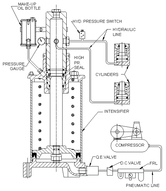 |
Figure 2  |
Accessories
- FRL - Filter, Regulator and Lubricator Unit.
- Filter to separate water from compressed air
- Regulator to regulate air pressure to 5 bar
- Lubricator - for lubrication of valves and the pneumatic seal of the intensifier
- D.C. Valve - Direction Control valve - (3/2 way valve)
- On position - Job gets clamped.
- Off position - Job gets de-clamped.
- Q.E. Valve - Quick Exhaust valve
- Use to increase de-clamping speed.
- Pneumatic line
- The hoses should withstand an air pressure up to 10 bar.
- Hydraulic line
- The hoses of R2 grade or metallic piping which should withstand an oil pressure up to 200 bar
- Metalic piping should be minimum with 8 mm ID to have quick return.
- Copper washers or bonded seals must be used with connectors.
- Pressure gauge
- Use glycerin filled gauges of 400 bar capacity.
Safety elements
Hydraulic Pressure Switch - The clamping force is directly proportional to the air pressure in the intensifier. Precaution must be taken to maintain this air pressure, and shut down the machine if the pressure is not sufficient. The pressure switch will shut down the machine, if the oil pressure drops below the preset value.
Points to remember while designing the system
- Keep the system as simple as possible.
- Keep minimum no. of connections in the circuit to avoid possibility of leakage.
- Try to minimize the hose length and use a quick exhaust valve to get a quick return stroke.
- Use bonded seals for leak proof connections.
- Keep the intensifier preferably at the highest points for easy bleeding.
- In case of a rigid piping, use a slant piping going towards intensifier for easy bleeding.
- For easier bleeding, avoid loops in hoses or rigid piping.
- In a hydropneumatic system, a flow control valve with a check valve can be used to achieve a delay in butting and clamping cylinders as shown in figure 2. Do not use more than one such valve in the circuit. Adjust the cracking pressure of the check valve to less than 0.3 bar.
- A single acting swing clamp should not be used after a sequence valve. Two separate intensifier circuits can be used for better sequencing.
- For hole punching, an external spring force should be applied in the hydropneumatic system as stripping out force is not available.
Selection of compressor
Compressed air requirement can be calculated as follows:
Compressed air volume required per cycle
= Intensification ratio x oil output.
e.g. For the intensifier of ratio 28 and oil output 100 cc,
air required per cycle = 28 x 100 = 2800 cc = 3 lit. approx.
If number of jobs per hour = 20 then air required per hour
= 3 x 20 = 60 lit / hour at 5 bar.